Description
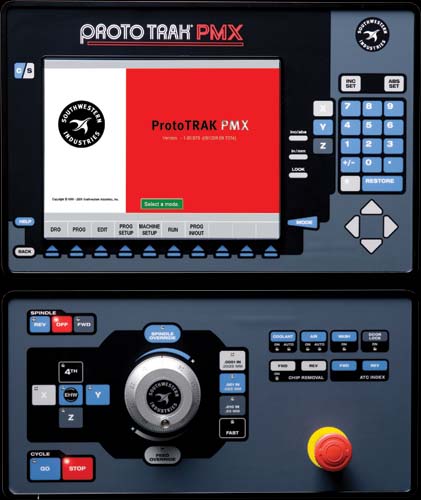
DRO Mode Features
- Incremental and absolute dimensions
- Jog with selectable feed rates
- Powerfeed X, Y or Z
- Servo return to 0 absolute
- Go To Dimensions from convenient reference
- Spindle speed setting with manual override
- Selectable handwheel resolution
- Convenient choice of dimensional references: Machine Home, Part Zero, Abs Zero Ball lock locations
Program Mode Features
- Auto Geometry Engine
- Geometry-based programming
- Tool Path programming
- Scaling of print data
- Multiple fixture offsets
- Programming of Auxiliary Functions
- Event Comments
- Three-axis Geometry conversational programming
- Incremental and absolute dimensions
- Automatic diameter cutter comp
- Circular interpolation
- Linear interpolation
- Look–graphics with a single button push
- List step – graphics with programmed events displayed
- Alphanumeric program names
- Program data editing
- Program pause
- Conrad – automatic corner radius
- Programmable spindle speeds
- Math helps with graphical interface
- Auto load of math solutions
- Tool step over adjustable for pocket routines
- Pocket bottom finish pass
- Selectable ramp or plunge cutter entry
- Subroutine repeat of programmed events
- Nesting
- Rotate about Z axis for skewing data
- Mirror of programmed events
- Copy
- Copy rotate
- Copy mirror
- Tool data entry in event programming
- Selectable retract in Bore operations
Auxillary Functions
- Coolant on/off
- Air on/off
- Pulse indexer
- Part change table position
Canned Cycles
- Position
- Drill
- Bolt Hole
- Mill
- Arc
- Circle pocket
- Rectangular pocket
- Irregular Pocket
- Circular profile
- Rectangular profile
- Irregular Profile
- Circle Island
- Rectangular Island
- Irregular Island
- Helix
- Thread milling
- Engrave
- Tapping
- Face Mill
Edit Mode Features
- Delete events
- Erase program
- Spreadsheet editing
- Global data change
- G-Code editor
- Clipboard to copy events between programs
- Move between subprograms in a master program
Program Set Up Mode Features
- Program diagnostics
- Advanced tool library
- Tool names
- Tool length offset with modifiers
- Tool path graphics with adjustable views
- Program run time estimation clock
- Convenient part/fixture management screen
- Fixture offsets
- Part offsets within fixture
- Convenient manual tool handling when tools required exceed ATC capacity
- Photo storage and display
- Notes
- Z Safety Dimension to prevent crashes
- Tool Crib
- Tool by Tool or Part by Part run strategy
- Convenient Tool Reconciliation between programs and ATC
- Convenient ATC capacity
Machine Set Up Mode Features
- Advanced diagnostic routines
- Software travel limits set in the factory
- Prompted Tool loading and ATC Management
- Checklist to assure nothing is forgotten
- Single key press to get to step needing attention
Run Mode Features
- TRAKing
- 3D CAM file program run
- 3D G code file run with tool comp
- Real time run graphics with tool icon
- Countdown clock for total part cycle time or manual tool change
- Error alarms prevent Run when set up steps are skipped
- Work on Staged programs while Current program runs
Program In/Out Mode Features
- CAM program converter
- Converter for prior-generation ProtoTRAK programs
- DXF/DWG file converter (Optional)
- Selection of file storage locations
- Automatic file back-up routine
- Preview graphics for unopened files
- Networking
- Create Master routine for combining programs
- Transfer of Staged program to Current
- Tool reconciliation for Master Programs
Control Options The DXF File Converter Option
- Import and convert CAD data into
- ProtoTRAK programs
- DXF or DWG files
- Chaining
- Automatic Gap Closing
- Layer control
- Easy, prompted process you can do right at the machine
CAM Out Converter Option
- Save ProtoTRAK files as CAM files for running on different controls
- 4th Axis Option
- True 4-axis interpolation.
Includes: indexer, tailstock and fixture plate.


